Reliable, standard-compliant valve calculation lays the foundation for proper equipment selection, long service life and system overpressure protection. As a professional industrial valve manufacturer, Xia Zhao Valve (Shanghai) strictly adopts global mainstream standards including ASME, API, ISO and IEC for all fluid, structural and actuator calculation. This guide corrects widespread formula errors in flow coefficient calculation and delivers verified engineering data, calculation examples and safety margins for global plant engineers, procurement teams and design institutes.
Flow coefficient Cv (US customary unit) and Kv (metric/European unit) are the core indicators for valve sizing. Many simplified formulas online contain wrong unit conversion and specific gravity definitions; below are official formulas released by ISA and IEC.
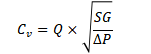
1.1Liquid Flow Coefficient
• Cv Formula (US standard: gpm, psi)
Q = liquid flow rate (gpm); SG = specific gravity (SG=1 for water); ΔP = pressure drop across valve (psi)
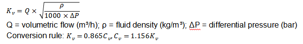
• Kv Formula (metric standard: m³/h, bar)
Engineering Example: Clean water flow 150 gpm, ΔP=10 psi, SG=1
Sizing rule: Reserve 10%–20% extra Cv margin, select valve with nominal Cv ≥ 52.
1.2 Pressure Drop Reverse Calculation
Calculate pressure loss after confirming valve Cv rating:
Industry practice: Design differential pressure of control valves accounts for 5%–25% of total system pressure to avoid cavitation damage and energy waste.
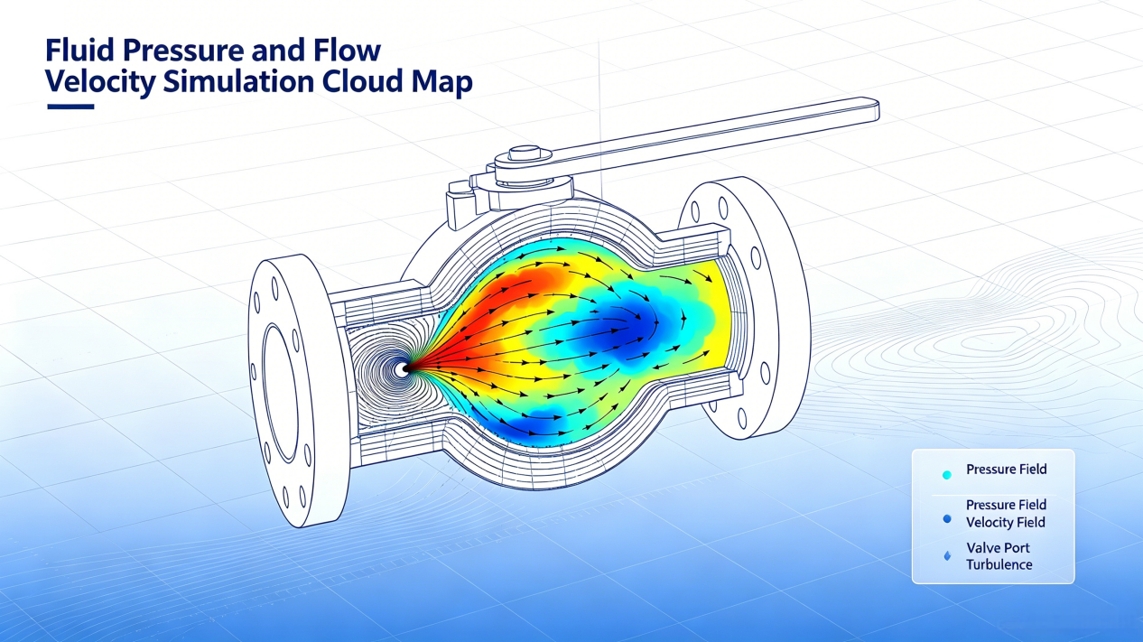
1.3 Flow Velocity Limitation (Anti-Erosion & Noise Control)
Flow velocity is a critical index to prevent valve erosion and excessive noise:
Recommended safe velocity thresholds:
• Clean water & light oil without abrasives: ≤10 m/s (33 ft/s)
• Slurry with solid particles: ≤5 m/s (16 ft/s)
• Normal-pressure gas: ≤30 m/s (98 ft/s); Mach number <0.3 for high-pressure gas
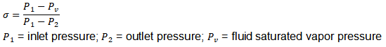
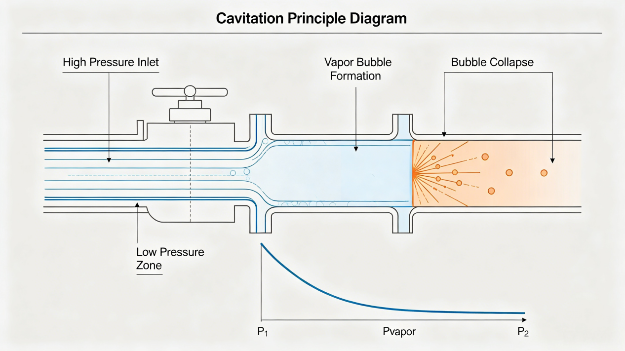
1.4 Cavitation Index σ Calculation & Risk Judgment
Cavitation index evaluates internal damage risk caused by pressure flashing and vaporization:
Risk Classification Standard:
σ>2.0: Safe operation, no cavitation 1.0<σ<2.0: Incipient cavitation, minor trim erosion σ<1.0: Severe cavitation & flashing, rapid valve failure Solution: Adopt multi-stage anti-cavitation trim or split two valves to reduce single-stage pressure drop.
2. Structural Strength Calculation per ASME B16.34
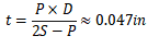
2.1 Minimum Body Wall Thickness (Barlow Thin-Wall Formula)
P = design pressure; D = pipe outer diameter; S = material allowable stress
Engineering Note: Theoretical Barlow calculation is only for reference. Actual wall thickness must follow ASME B16.34 standard table based on pressure class, which sets mandatory minimum thickness higher than theoretical value to ensure safety. Typical allowable stress: WCB carbon steel 20,000 psi @ ambient temp; 304 stainless steel 18,750 psi.
2.2 Stem Shear Stress Verification
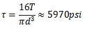
Solid round stem shear stress formula:
T = operating torque; d = stem outer diameter Mandatory safety factor ≥3; Xia Zhao adopts 4~5 for all industrial valves to extend service life.
Engineering Case: 0.75” 304 SS stem with torque 500 lb-in, shear stress = 6,032 psi, yield strength 30,000 psi, safety factor ≈5, fully compliant with industrial standards.
2.3 Seat Specific Sealing Pressure
Seat specific pressure ensures bubble-tight shutoff against hydraulic opening thrust:
, q must exceed internal medium pressure
Standard Specific Pressure Range:
• Soft seat (PTFE, PEEK): 0.5–1.0 MPa (73–145 psi)
• Metal-to-metal seat (gate, globe valve): 2–5 MPa (290–725 psi)
Excessively high specific pressure accelerates seat wear; Xia Zhao balances tightness and service life in customized design.
3. Actuator Torque & Thrust Sizing Calculation
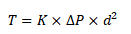
3.1 Manual Valve Empirical Torque Formula
K = empirical coefficient 0.01~0.015 N·m/(bar·mm²); d = nominal bore (mm) Operation Limit: Manual handwheel torque shall not exceed 300 N·m for comfortable operation; gearbox or pneumatic actuator is required for higher torque demand.
3.2 Actuator Sizing Safety Margin
Pneumatic actuator thrust:F=supplypressure*pistonarea,safety factor 1.5~2.0
Electric actuator power formula:P(kw)=(T*N/9550), actuator rated torque ≥1.5 times valve required torque.
4. Special Extreme Condition Calculation & Standard Engineering Cases
This chapter provides fully verified practical calculation cases covering conventional sizing, structural verification and extreme working conditions, guiding global engineers in real project application.
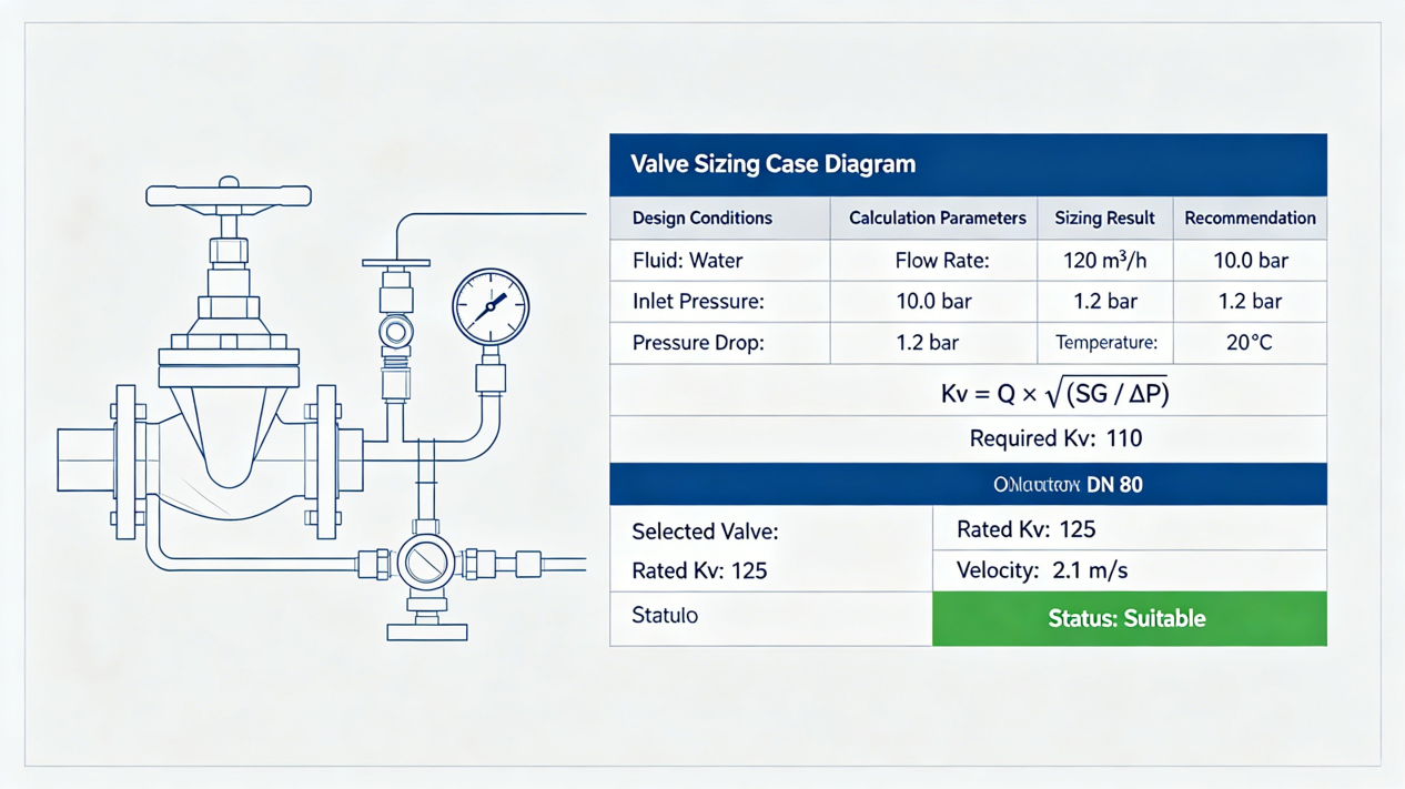
4.1 Conventional Valve Sizing Full Calculation Case
Working Condition: Chemical clean water pipeline, room temperature water (SG=1.0, ρ=1000kg/m³), design flow Q=200gpm, system pressure drop ΔP=8psi, carbon steel globe valve for general service.
Step 1: Cv Value Calculation
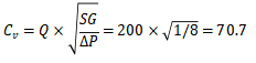
Step 2: Safety Margin Sizing
Adopt 15% industry standard safety margin, required Cv=70.7×1.15≈81.3. Select DN100 carbon steel globe valve with nominal Cv≥82.
Step 3: Actual Pressure Drop Verification
With rated Cv=82, actual operating pressure drop: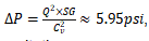
, within the optimal 5%–25% system pressure drop range, no cavitation or energy waste risk.
Step 4: Flow Velocity Check
The flow velocity of the selected valve is 2.8m/s, far below the 10m/s safety threshold for clean water, effectively avoiding erosion, vibration and excessive noise.
4.2 Valve Body Wall Thickness Verification Case (ASME B16.34)
Working Condition: Class150, NPS6 WCB carbon steel valve, design pressure P=285psi, outer diameter D=6.625in, allowable stress S=20000psi.
Compliance Judgment: The mandatory minimum wall thickness specified by ASME B16.34 for this valve is 0.19in, which is significantly higher than the theoretical value. The valve body fully meets international pressure-bearing safety standards.
4.3 Stem Shear Strength Verification Case
Working Condition: 304 SS solid stem, diameter d=0.8in, maximum operating torque T=600lb-in, yield strength=30000psi, required safety factor ≥4.
Safety Verification: Actual safety factor ≈5.02, exceeding the standard requirement. The stem has no deformation or shear failure risk under full-load operation.
4.4 Extreme Working Condition Calculation Rules
• Cryogenic service (-196℃ liquid nitrogen/oxygen) Thermal contraction:
304 SS linear expansion coefficient α=16×10⁻⁶/℃, 500 mm stem contracts 1.6 mm at -196℃; design clearance ≥2 mm to prevent stem jamming.
• High-temperature service (up to 600℃ steam) Bolt preload loss caused by temperature difference; disc spring compensation and graphite spiral wound gaskets are applied to maintain tightness.
• Corrosion & abrasion estimation Acceptable corrosion rate ≤0.1 mm per year; abrasion depth positively correlates with square of flow velocity and solid concentration. Stellite hard surfacing is adopted on disc and seat for slurry media.
5. Global Standards for Valve Calculation
ASME B16.34: Pressure-temperature ratings & wall thickness
API 598: Valve inspection & leakage test
IEC 60534: Control valve sizing
API 520 / API 526: Safety valve relief capacity calculation
ISO 4126: Safety & relief devices general standard
Safety Valve Sizing Calculation & Standard Certified Calculation Document Specification
SEO Keywords: safety valve sizing API 520, relief valve orifice area, ASME Section VIII safety valve calculation, safety valve calculation sheet
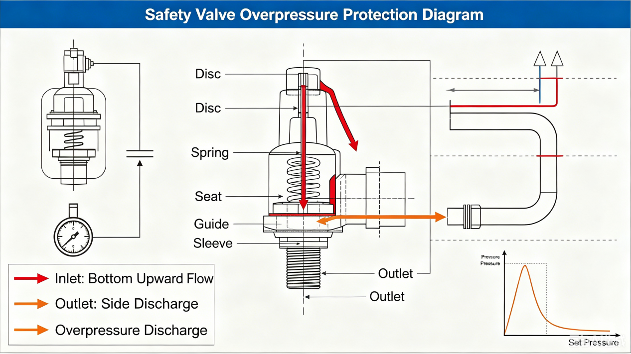
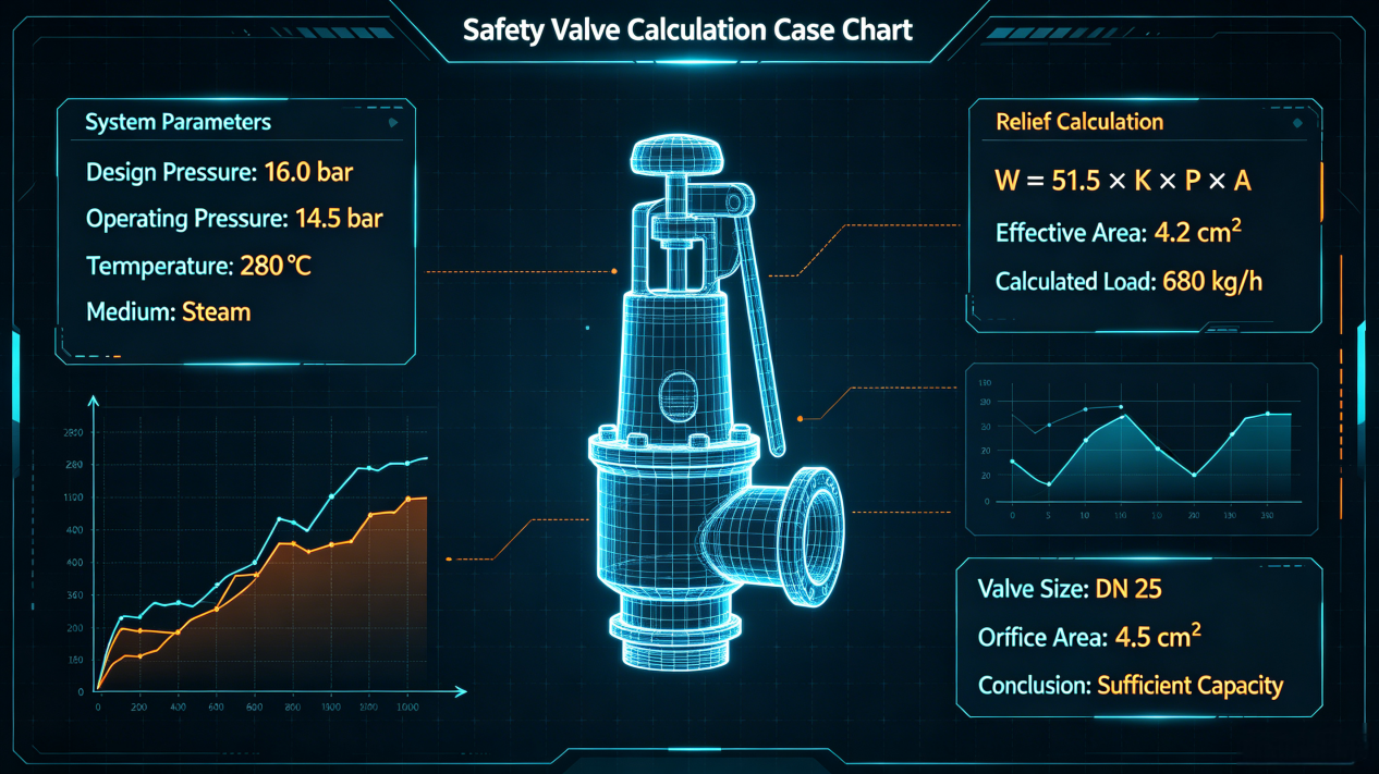
Safety valves act as the ultimate overpressure protection barrier for pressure vessels, boilers and piping systems. Incorrect sizing leads to vessel explosion risk or unnecessary frequent popping. All safety valve calculation documents manufactured by Xia Zhao Valve strictly comply with API 520 Part I/II, API 526 and ASME BPVC Section VIII Div.1. This article introduces full calculation workflow for gas, vapor and liquid relief, as well as standard specification of official certified calculation reports for global clients.
1. Confirm Required Relief Mass Flow Rate
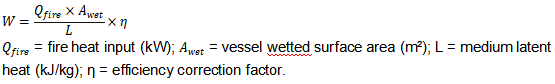
Define the worst-case overpressure scenario (fire heat input, blocked outlet, thermal expansion of trapped liquid) to calculate minimum required relief flow W (kg/h or lb/h). Fire case calculation for liquid-filled vessels (API 521):
2. Pressure Parameters & Backpressure Correction
1. Set pressure pset:Pressure where valve starts to lift;
2. Allowable overpressure: 10% for single safety valve, 21% for fire emergency condition;
3. Total inlet relief pressure P1=Pset+overpressure+atmosphericpressure
4. Total backpressure P2= superimposed constant backpressure + built-up dynamic backpressure.
Balanced bellows safety valves require extra backpressure correction factor Kb during orifice area calculation.
3. Required Orifice Area Calculation & Engineering Cases
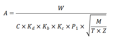
3.1 Gas & Vapor Critical Flow Calculation (API 520 Standard Formula)
Parameter Definition (SI Unit):
C: Gas constant determined by specific heat ratio k (air k=1.4, C=356)
K d: Discharge coefficient (0.975 for ASME certified safety valves)
K b: Backpressure correction factor (derived from API 520 table, less than 1.0)
K c: Rupture disc combination correction (0.9 with rupture disc, 1.0 without)
M: Fluid molecular weight (kg/kmol); T: Inlet absolute temperature (K); Z: Compressibility factor
Calculation Example (Propane Vapor): W=5000 kg/h, M=44.1, T=323K, Z=0.9, P₁=15 bar(a), Kb=0.92, C=327
Calculated required orifice area ≈3.42 cm², select next standard API 526 orifice size (Model E/F).
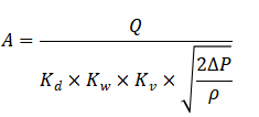
3.2 Liquid Relief Sizing Formula
ΔP = P₁-P₂ differential pressure;
K w= viscosity correction (1.0 for low-viscosity liquid);
K v= liquid discharge coefficient (~0.6 for conventional safety valves).
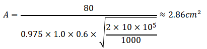
3.3 Liquid Medium Safety Valve Sizing Case
Working Condition: Industrial water pressure vessel, liquid water (ρ=1000kg/m³), required relief flow Q=80m³/h, inlet pressure P₁=12bar, backpressure P₂=2bar, low viscosity medium, no rupture disc.
Parameter Confirmation: Kd=0.975, Kw=1.0, Kv=0.6, ΔP=10bar
Orifice Area Calculation:
Final Selection: Reserve 20% safety margin, required area=3.43cm², select API standard F-type orifice safety valve to meet liquid overpressure relief requirements.
4. API Standard Orifice & Material Selection Rules
1. Standard orifice series (API 526): Range from D (0.110 in²) to T (26 in²), select larger size with 15%–20% area safety margin for operating uncertainty;
2. Trim material matching: 316SS for general corrosive medium, Hastelloy/Monel for strong acid/alkali, Inconel X-750 spring for high temperature up to 600℃ steam.
5. Certified Safety Valve Calculation Document Standard
All calculation reports supplied by Xia Zhao Valve comply with international third-party inspection and project acceptance standards. The official certified sizing sheet includes the following standardized modules:
1. Basic project data: Medium, design temperature, set pressure, vessel working condition;
2. Overpressure scenario definition (fire/blocked outlet/thermal expansion);
3. Full flow rate derivation process with all intermediate values;
4. Backpressure correction table & factor selection basis;
5. Orifice area calculation full formula & numerical substitution process;
6. Standard orifice model selection comparison table;
7. Material temperature resistance & trim compatibility verification;
8. Compliance statement: API 520, API 526, ASME VIII certification mark;
9. Manufacturer signature, engineering stamp, factory serial number traceability.
6. Professional Engineering Suggestions for Global Users
1. Reserve minimum 15%~20% extra orifice area to cover uncertain operating fluctuations;
2. Steam service quick sizing shortcut (Napier formula, US unit):
3. Confirm backpressure upper limit before ordering: Conventional bellows valves tolerate backpressure up to 10%~50% of set pressure;
4. Custom certified calculation sheets and professional sizing consultation are available for global oil, chemical and power plant projects.


 Hot News