
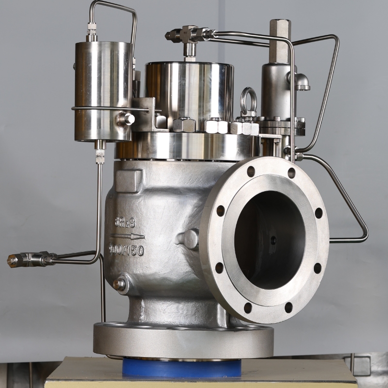
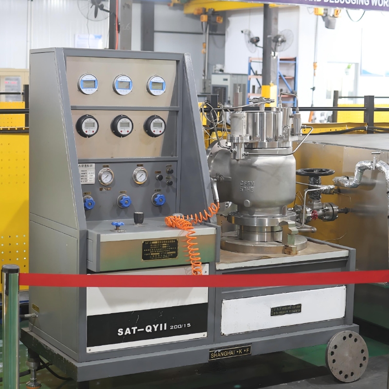
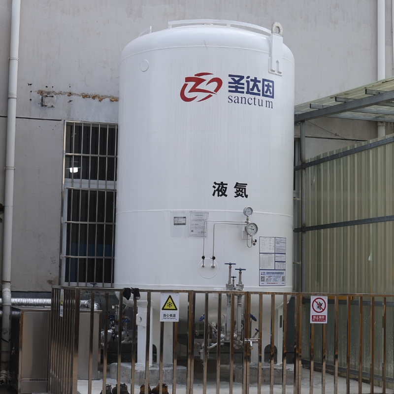
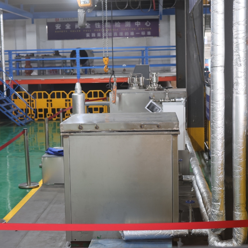
Precision engineered for LNG, Liquid Nitrogen (LIN),Liquid Oxygen
(LOX),Liquid Argon (LAr), and Ethylene cryogenic storage tanks &
liquefaction plants. Features a self-tightening dome pressure mechanism
that delivers zero-bubble seat tightness up to 98% of set pressure with
thermal decoupling anti-icing protection.
√ Extreme Low Temp: -196°C to +80°C
√ Zero Bubble Leakage @ 98% Set p
√ Low Blowdown: ≤ 7%
√ Anti-Freeze Thermal Decoupling
√ High Backpressure lmmunity
|
Manufacturer |
Shanghai Xiazhao Valve Co., Ltd. |
Operating Temp |
-196°C to +80°C (-320°F to +176°F) |
|
Core Certifications |
ISO 4126-4 / GB/T 40011 / CE PED Module B+D |
Seat Tightness |
Zero Bubble @ 98% Set P (API 527) |
|
Pressure Rating |
Class 150 ~ 2500 (PN16 ~ PN420) |
Nominal Diameter |
DN25 ~ DN300 (1" ~ 12" NPS) |
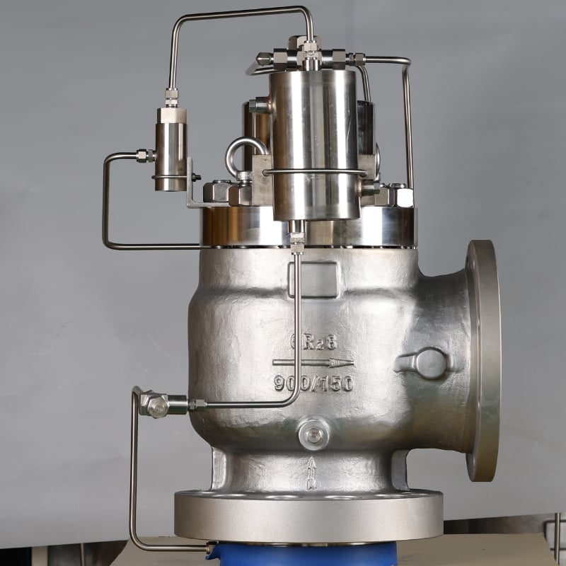
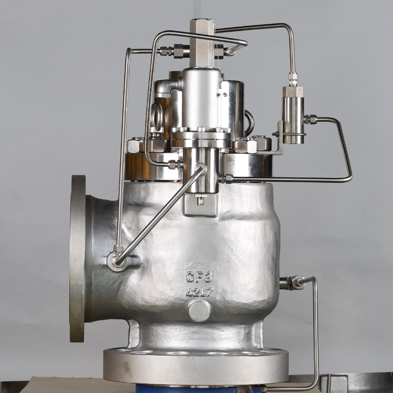
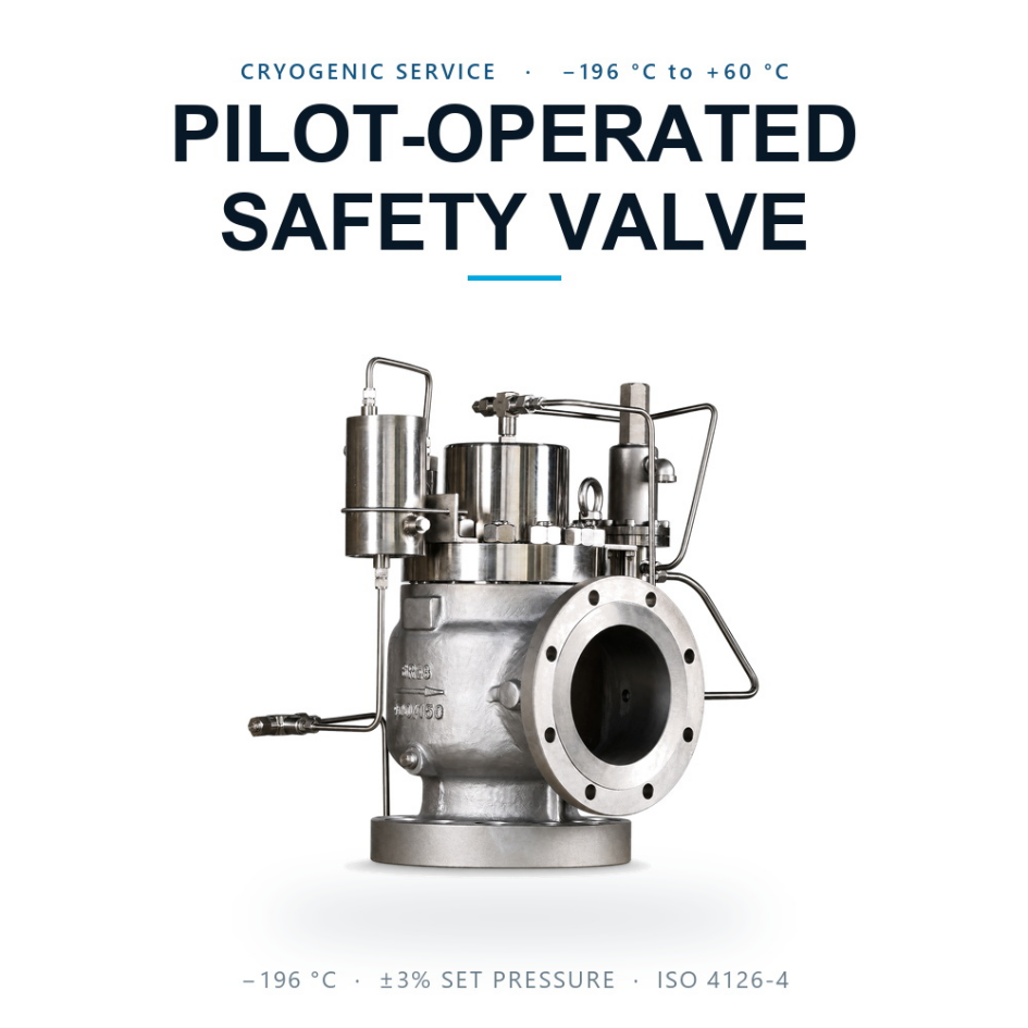
The XZ-790LP-Cryo cryogenic pressure relief valve is a pilot-operated pressure-relief assembly described for low-temperature process systems. The supplied product material lists an operating temperature range of -196°C to +80°C, making this cryogenic pressure relief valve relevant to applications where low-temperature media, pressure control, and compatible materials must be considered together. It is presented as a pilot-operated safety valve with a main valve body, differential-area piston, and external non-flowing pilot.
The source describes this valve for LNG, liquid nitrogen, liquid oxygen, liquid argon, cryogenic ethylene, and related cold hydrocarbon duties. A listed application does not by itself establish suitability for a particular installation; the selected valve should match the actual medium, temperature, pressure, discharge arrangement, and connection requirements of the system.
| Listed item | Source-listed information |
|---|---|
| Product series | XZ-790LP-Cryo pilot-operated pressure relief valve |
| Operating temperature | -196°C to +80°C (-320°F to +176°F) |
| Set pressure range | 0.10 MPa to 42.0 MPa (14.5 PSI to 6090 PSI) |
| Nominal sizes | DN25 to DN300 (1 in to 12 in NPS) |
| Orifice range | API 526 letters D through T |
| Flange options | RF or RTJ; inlet Class 150 to 2500, outlet Class 150 or 300 |
The listed range is a starting point, but the final configuration depends on set pressure, required relieving capacity, inlet and outlet geometry, backpressure, and the discharge path. For API 526 orifice sizing, match the required orifice letter and flow area to the duty rather than line size alone.
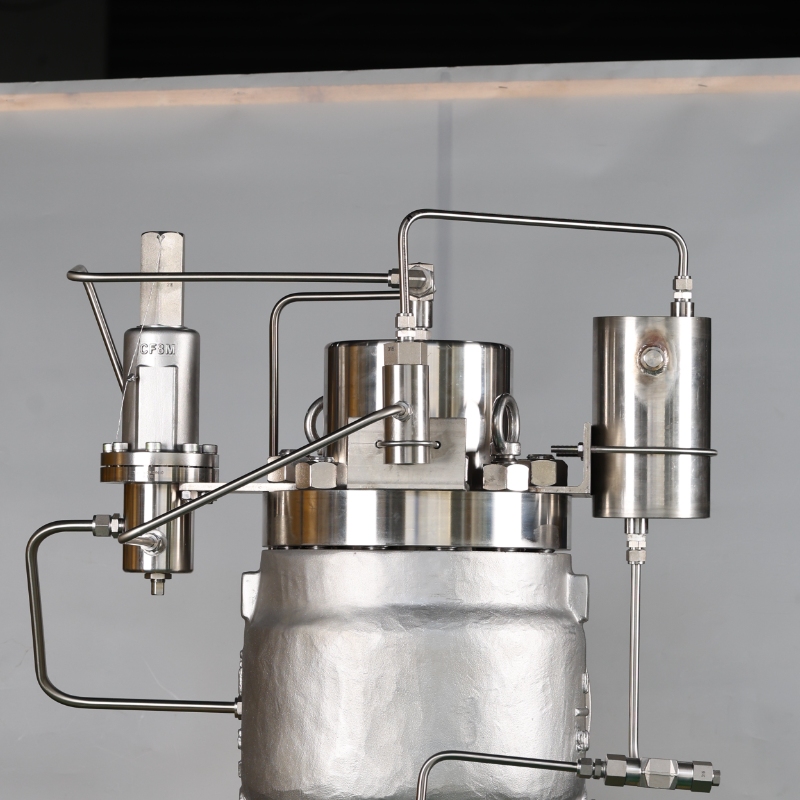
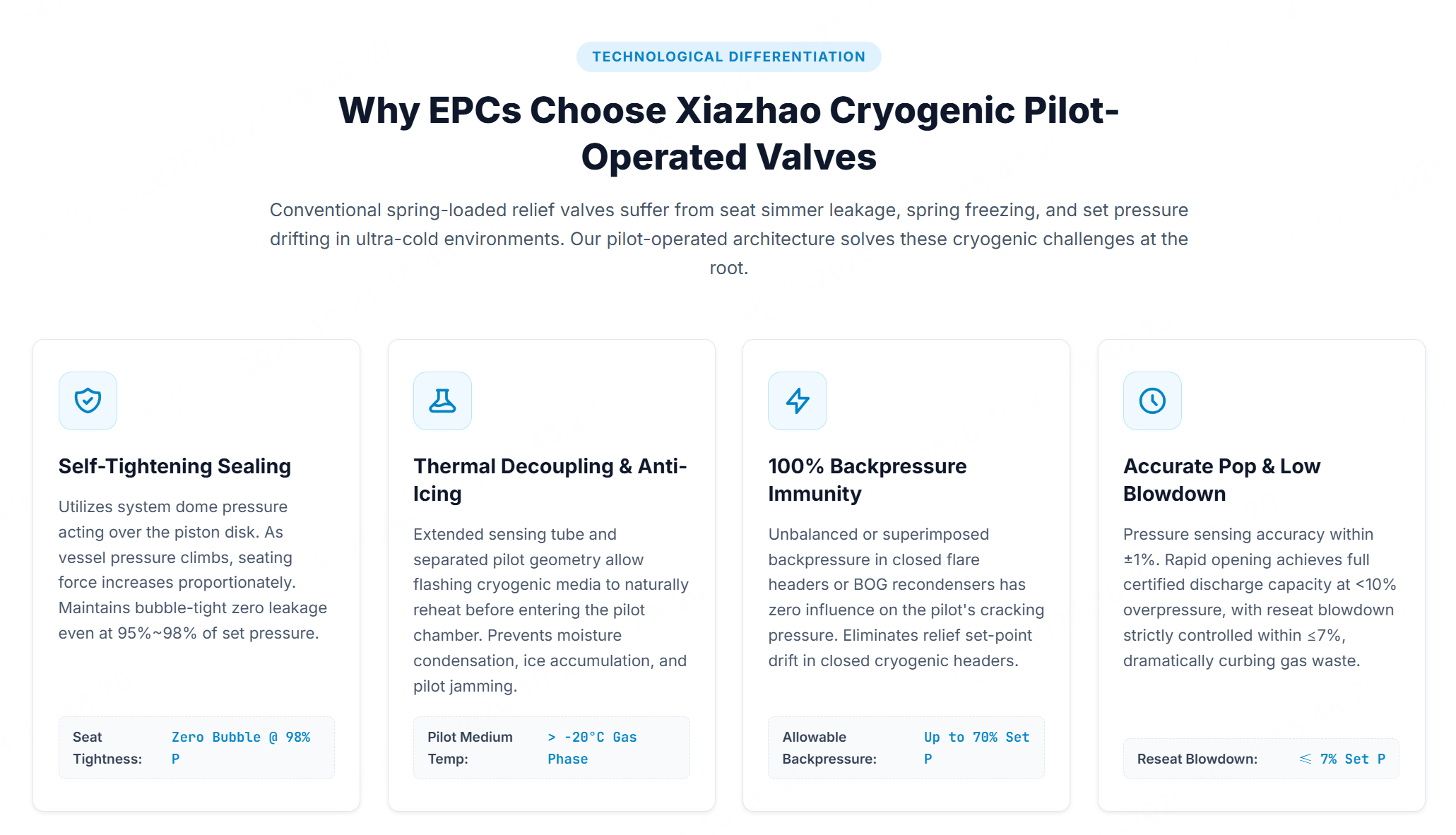
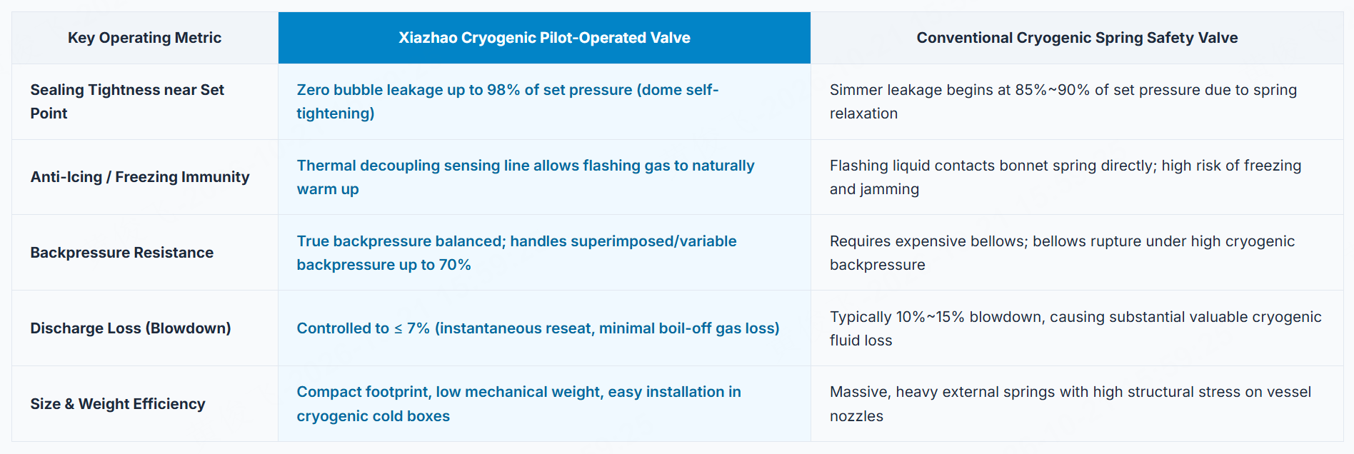
According to the supplied description, the pilot-operated assembly uses dome pressure and differential area to support sealing during normal operation. At set pressure, the pilot is described as venting the dome so the main piston can lift; as pressure decreases, it restores dome pressure to support reseating. Final behavior depends on the selected configuration and system conditions.
The source lists zero-bubble seat tightness at 90%, 95%, and 98% of set pressure under API 527 terminology, together with blowdown of no more than 7%. It also describes a balanced, non-flowing pilot design for variable backpressure up to 70% of set pressure. Confirm the required duty and documentation for an individual order.
For LNG storage and receiving equipment, a cryogenic pressure relief valve may be considered where a relief path is required around cold tanks, BOG handling loops, or associated piping. The source also identifies LNG BOG relief system applications. The actual arrangement needs to account for medium condition, set pressure, discharge routing, and the connected equipment; these details shape the correct valve configuration.
For air separation equipment and cryogenic storage, the product is described for liquid nitrogen and liquid argon service. Low-temperature compatibility involves the body, seals, pilot tubing, pressure sensing, flanges, and installation conditions. A clear inquiry should identify the medium, operating temperature, design pressure, set pressure, and connection standard.
For liquid oxygen and cold hydrocarbon service, the supplied product details describe specific material and clean-service references. A cryogenic pressure relief valve for these duties should be discussed with the requested material configuration and documentation scope. Where a project calls for ISO 4126-4 certified equipment, the certificate scope, applicable configuration, and documentation requirement should be confirmed for the actual supply.
The supplied matrix lists several body and trim combinations. For example, stainless, low-temperature cast steel, and Monel-related options appear in different positions within the material table, while seal choices include F46, PCTFE, PTFE, and other materials. This means the cryogenic pressure relief valve can be configured around the stated service requirements, but it also means an available option should not be read as a standard feature on every unit.
API 526 orifice sizing is another configuration point. The source lists letters D through T and provides a dimensional matrix that links nominal inlet and outlet sizes to orifice ranges, flow areas, pressure classes, and set-pressure ranges. A cryogenic pressure relief valve request is more actionable when it includes required relieving conditions, rather than only a nominal pipe size or a broad service description.
To discuss a configuration, provide the medium, operating and design temperatures, set pressure, required capacity, inlet and outlet size, pressure class, flange facing, and preferred documentation. For an LNG BOG relief system, include the process conditions and discharge arrangement. If ISO 4126-4 certified documentation is required, state the project requirement.
The XZ-790LP-Cryo is presented for low-temperature pressure-relief duties. Its listed temperature range, pilot-operated principle, pressure range, connection options, materials, and standards references provide a basis for a focused inquiry. Contact the technical team with service data to identify a configuration for the intended installation.
Installation details such as impulse-line routing, pilot accessibility, insulation interfaces, and outlet support should be considered with the surrounding equipment. The product information identifies connection and material options, while the final arrangement should reflect the specified process duty, piping layout, and applicable site requirements for the intended installation at hand.
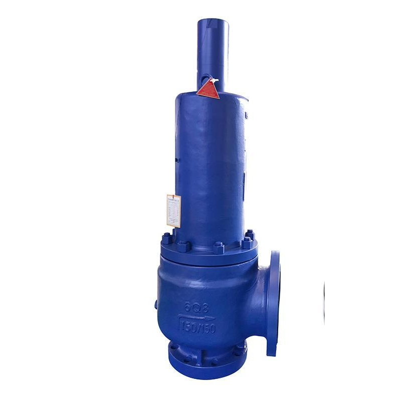
Products Number: API 526 Liquid Relief Valve – 150LB 6Q8 – WCB Body & 316 Trim – Steam/Gas Compatible – Adjustable Set Pressure
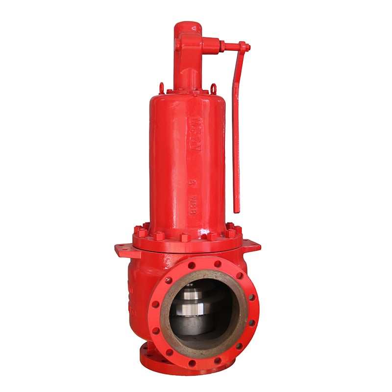
Products Number: Industrial Large Size Safety Valve – API 526 8T10 – 300LB WCB & 316 Trim – Reliable Overpressure Protection for Chemical Plants
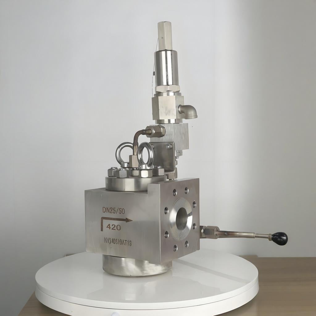
Products Number: Pilot-Operated Safety Valve—Snap-acting DIN

Products Number: Industrial High-Pressure Relief Valve | Safety & Performance
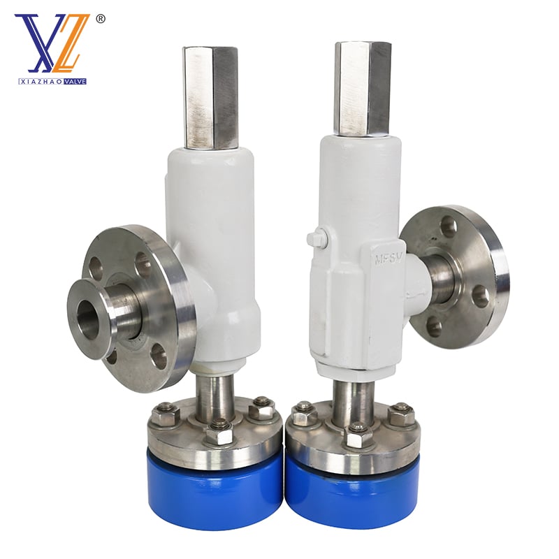
Products Number: TOSX & TOSBX Loose Flange Pressure Relief Valve – Flexible Installation & High Backpressure Stability
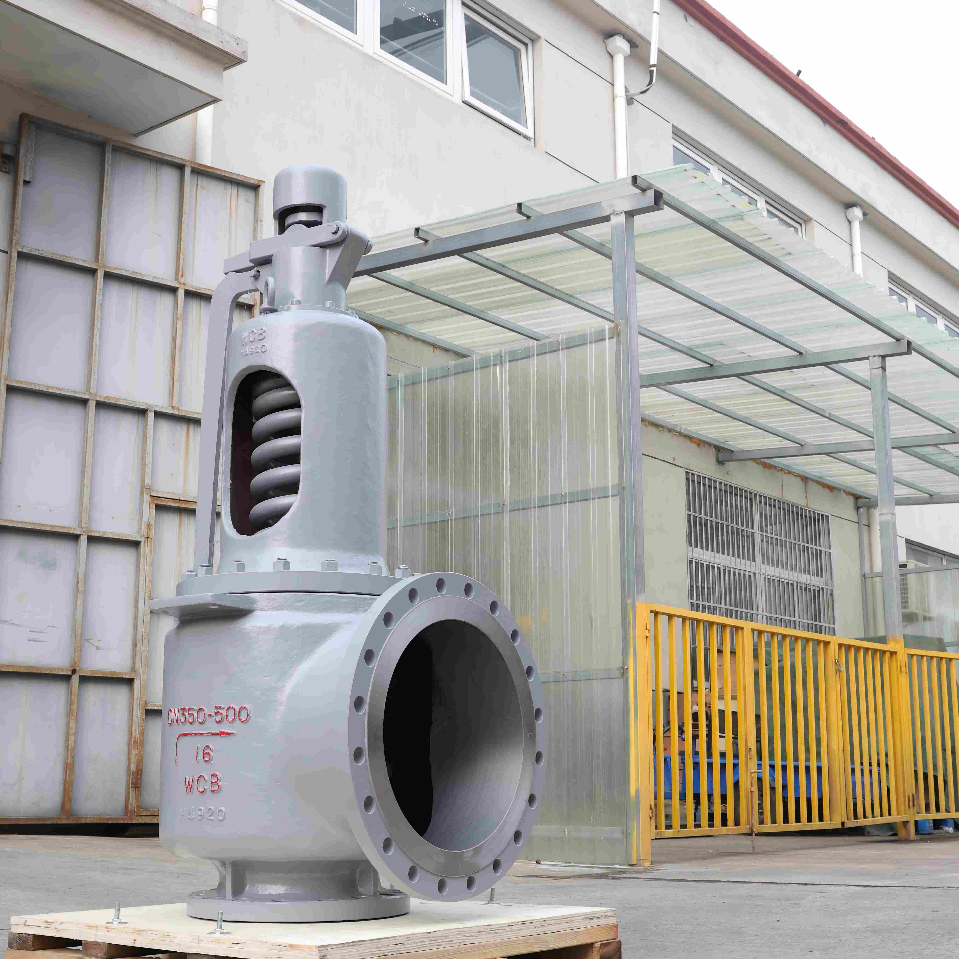
Products Number: DN350*500 High-Performance Steam Pressure Relief Valve


Shanghai Xiazhao Valve Co., LTD. provides high-performance ball and safety valves for petrochemical, natural gas, and industrial automation. Our API 6D, ANSI 600LB, and fire-safe designs ensure reliability. 95% on-time delivery. Request a quote.
Building 12, 6133 Huyi Road, Jiading District, Shanghai
Copyright © 2026 China Shanghai Xiazhao Valve Co., LTD. All rights reserved. Privacy Policy
 EN