
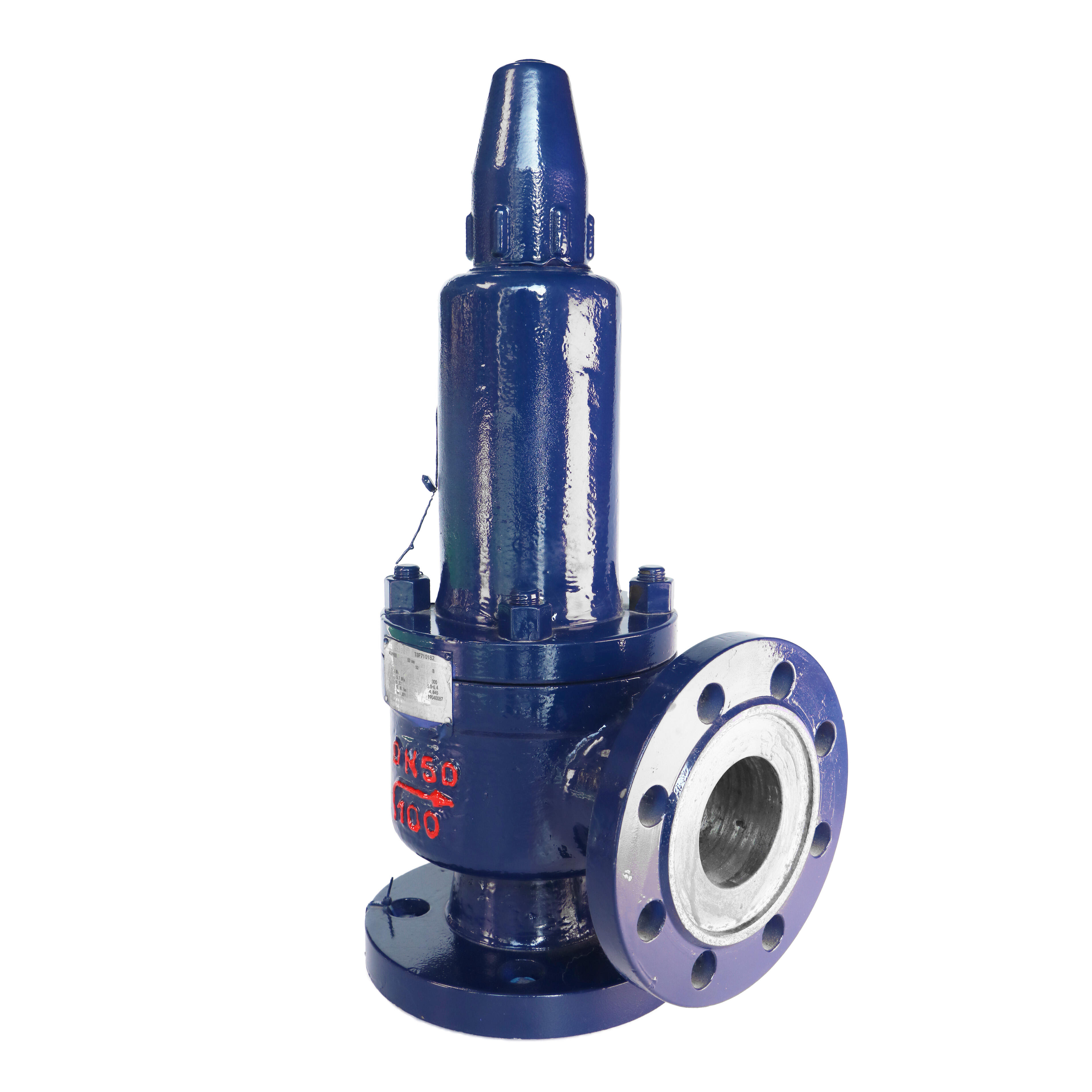
Industrial facilities across oil and gas, petrochemical, and power generation sectors rely on robust pressure protection systems to maintain operational safety and equipment integrity. A spring loaded relief valve serves as the critical first line of defense against potentially catastrophic overpressure conditions that can damage expensive equipment, compromise personnel safety, and lead to costly operational shutdowns. These precision-engineered safety devices automatically open when system pressure exceeds predetermined set points, providing immediate pressure relief while maintaining the structural integrity of downstream equipment and piping systems.
The fundamental design principle behind these pressure relief mechanisms centers on a carefully calibrated spring mechanism that responds predictably to pressure variations. Unlike other types of relief systems, spring-actuated designs offer consistent performance characteristics across varying temperature ranges and provide reliable operation without requiring external power sources or control systems. This inherent reliability makes them particularly valuable in remote locations or critical applications where power interruptions could compromise safety system functionality.
Engineering Principles and Design Architecture
Spring Mechanism Fundamentals
The core operational principle of a spring loaded relief valve relies on the precise balance between inlet pressure force and spring compression force acting on the valve disc or poppet. When system pressure rises above the spring's predetermined set point, the upward pressure force overcomes the downward spring force, allowing the valve to lift and release excess pressure. This mechanical advantage system ensures rapid response times, typically opening within milliseconds of reaching the set pressure threshold.
Modern spring relief valve designs incorporate advanced metallurgy and precision machining techniques to achieve consistent spring characteristics over extended operating periods. The spring itself undergoes specialized heat treatment processes to maintain its compression properties under cyclic loading conditions. Quality manufacturers employ finite element analysis during the design phase to optimize spring geometry and ensure uniform stress distribution across the entire spring length.
Material Selection and Construction
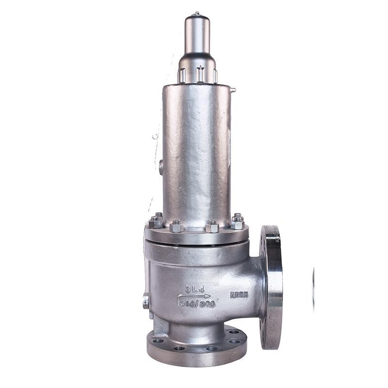
High-performance relief valves utilize carbon steel bodies with stainless steel trim configurations to provide exceptional corrosion resistance and mechanical strength. The WCB (cast carbon steel) body material offers excellent weldability and machinability while maintaining structural integrity under high-pressure conditions. Internal components, including seats, discs, and springs, typically feature 316 stainless steel construction to resist chemical attack from aggressive process fluids.
Critical wear surfaces receive specialized treatments such as stellite overlay welding or carbide coating to extend service life and maintain precise sealing characteristics. These surface treatments prove particularly important in applications involving abrasive media or high-cycle operating conditions where repeated valve actuation could cause premature wear.
Industrial Applications and Performance Characteristics
Oil and Gas Sector Implementation
Upstream oil and gas operations depend heavily on reliable pressure protection systems to safeguard expensive wellhead equipment, separation vessels, and pipeline infrastructure. A properly sized spring loaded relief valve provides immediate response to pressure transients caused by thermal expansion, equipment malfunction, or process upsets. These valves must maintain tight shutoff characteristics to prevent product loss while providing full-flow capacity when relief conditions occur.
Offshore platforms present unique challenges including saltwater corrosion, extreme weather conditions, and limited maintenance access. Relief valves in these environments require enhanced material specifications and robust construction to ensure reliable operation throughout extended service intervals. The ability to function without external power or control systems makes spring-actuated designs particularly suitable for these demanding applications.
Petrochemical Processing Requirements
Chemical processing facilities handle a wide variety of corrosive and toxic substances that demand specialized relief valve configurations. Spring loaded relief valve designs accommodate these requirements through careful material selection and internal component optimization. The combination of carbon steel body construction with corrosion-resistant trim provides the necessary chemical compatibility while maintaining cost-effectiveness for large-scale installations.
Temperature cycling represents another significant challenge in petrochemical applications, as process conditions frequently vary between ambient and elevated temperatures. Relief valve springs must maintain consistent set pressure characteristics across this temperature range to ensure reliable protection. Advanced spring alloys and specialized heat treatment processes enable modern relief valves to achieve this performance requirement.
Technical Specifications and Standards Compliance
API 526 Certification Requirements
The American Petroleum Institute Standard 526 establishes comprehensive requirements for flanged steel pressure relief valves used in petroleum and chemical service. This standard specifies dimensional requirements, material specifications, testing procedures, and marking requirements that ensure consistent performance across different manufacturers. Compliance with API 526 provides end users with confidence in valve reliability and interchangeability.
Key aspects of API 526 compliance include standardized inlet and outlet flange dimensions, minimum flow coefficient requirements, and set pressure tolerance specifications. The standard also mandates specific material requirements for body construction and internal components to ensure compatibility with typical petroleum industry applications. Regular third-party testing and certification verify continued compliance throughout the manufacturing process.
Pressure Rating Classifications
Industrial relief valves are available in various pressure class ratings to accommodate different system operating pressures. The 600 lb pressure class represents a common specification for medium to high-pressure applications in oil, gas, and petrochemical service. This pressure rating provides adequate safety margin for systems operating at pressures up to 1440 PSIG at ambient temperature, with appropriate derating for elevated temperature service.
Higher pressure classes such as 900 lb, 1500 lb, and 2500 lb are available for specialized applications requiring greater pressure capability. The selection of appropriate pressure class depends on maximum anticipated system pressure, temperature conditions, and applicable safety factors specified by relevant design codes and standards.
Installation and Maintenance Considerations
Proper Installation Practices
Correct installation procedures are essential for ensuring optimal relief valve performance and service life. The valve inlet must be connected to the protected system through properly sized piping that minimizes pressure drop between the system and the valve inlet. Inlet piping should be as short and direct as possible, avoiding unnecessary fittings, bends, or restrictions that could affect valve performance.
Outlet piping design requires careful attention to prevent excessive back pressure that could interfere with valve operation. The discharge piping must be sized to handle the full relief capacity of the valve while maintaining back pressure below the manufacturer's specified limits. Proper support of inlet and outlet piping prevents excessive stress on the valve body that could affect sealing performance or structural integrity.
Preventive Maintenance Programs
Regular maintenance is crucial for maintaining spring loaded relief valve reliability and ensuring continued compliance with safety requirements. Typical maintenance intervals range from annual to every five years, depending on service conditions and regulatory requirements. Maintenance activities include visual inspection of external components, verification of set pressure through bench testing, and replacement of sealing elements and springs as needed.
Spring condition assessment represents a critical aspect of relief valve maintenance, as spring degradation can cause set pressure drift or complete failure to open. Modern testing facilities utilize calibrated test equipment to verify spring characteristics and overall valve performance under simulated operating conditions. Documentation of test results provides evidence of continued compliance with safety requirements and helps identify trends that may indicate developing problems.
Performance Optimization and Troubleshooting
Flow Coefficient and Sizing Considerations
Proper sizing of spring loaded relief valve installations requires accurate calculation of required relief capacity and selection of appropriate flow coefficient values. The valve must provide sufficient flow area to handle maximum anticipated relief flow while maintaining acceptable pressure rise above the set point. Undersized valves may not provide adequate protection, while oversized valves may exhibit poor sealing characteristics or unstable operation.
Flow coefficient calculations must account for the specific properties of the process fluid, including molecular weight, compressibility effects, and temperature conditions. Gas and vapor applications require different calculation methods compared to liquid service, with compressible flow effects becoming significant at higher pressure ratios. Professional engineering analysis ensures accurate sizing and optimal valve selection for each specific application.
Common Operating Issues and Solutions
Relief valve troubleshooting often involves addressing issues such as premature opening, failure to open at set pressure, or excessive seat leakage during normal operation. Premature opening may result from inlet pressure pulsations, thermal effects on the spring, or contamination affecting the sealing surfaces. Proper installation practices and regular maintenance help prevent many of these common problems.
Seat leakage problems typically stem from contamination, thermal cycling damage, or mechanical wear of sealing surfaces. Modern relief valve designs incorporate features such as soft seat inserts or lapped metal seats to minimize leakage while maintaining reliable operation. When leakage problems occur, prompt maintenance action prevents escalation to more serious operational issues.
FAQ
What is the typical service life of a spring loaded relief valve in industrial applications
The service life of industrial spring loaded relief valves typically ranges from 5 to 15 years, depending on operating conditions, maintenance practices, and service environment. Valves in clean, non-corrosive service with infrequent actuation may achieve longer service intervals, while those exposed to harsh chemicals, high temperatures, or frequent cycling may require more frequent replacement. Regular maintenance and testing help maximize service life and ensure continued reliable operation.
How do environmental conditions affect spring loaded relief valve performance
Environmental conditions significantly impact relief valve performance, with temperature extremes affecting spring characteristics and set pressure accuracy. Cold temperatures can increase spring stiffness and raise the effective set pressure, while high temperatures have the opposite effect. Corrosive atmospheres can cause external corrosion and affect valve operation, while vibration from nearby equipment may cause premature wear or seal deterioration. Proper material selection and installation practices help mitigate these environmental effects.
What are the key differences between spring loaded and pilot operated relief valves
Spring loaded relief valves use direct spring force to control opening pressure and provide simple, reliable operation without external controls or power sources. Pilot operated valves use system pressure acting on a larger area to provide greater sensitivity and tighter shut-off characteristics, but require more complex internal mechanisms. Spring loaded designs are generally preferred for smaller sizes and general-purpose applications, while pilot operated valves excel in large capacity applications or where precise pressure control is required.
How should relief valve discharge piping be designed to ensure proper operation
Relief valve discharge piping must be sized to handle full valve capacity while maintaining back pressure below manufacturer specifications, typically 10% of set pressure for conventional valves. The piping should slope continuously upward from the valve outlet to prevent liquid accumulation, and must be adequately supported to prevent stress on the valve body. Discharge piping should terminate in a safe location away from personnel and equipment, with appropriate weather protection and drainage provisions for outdoor installations.
Table of Contents
- Engineering Principles and Design Architecture
- Industrial Applications and Performance Characteristics
- Technical Specifications and Standards Compliance
- Installation and Maintenance Considerations
- Performance Optimization and Troubleshooting
-
FAQ
- What is the typical service life of a spring loaded relief valve in industrial applications
- How do environmental conditions affect spring loaded relief valve performance
- What are the key differences between spring loaded and pilot operated relief valves
- How should relief valve discharge piping be designed to ensure proper operation