EN

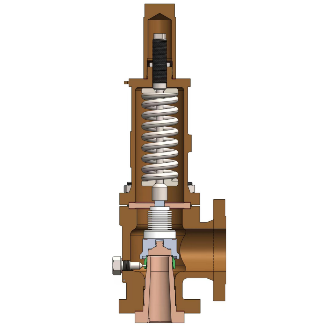
A pressure relief valve is the last line of defense against overpressure in pressure vessels and piping systems. API 520 (Part I and Part II) governs the sizing, selection, and installation of pressure-relieving devices in the petroleum refining and related industries. API 521 provides the engineering methodology for identifying overpressure scenarios and designing relieving systems. API 526 standardizes the orifice areas, dimensions, and pressure ratings of flanged steel pressure-relief valves. This article, written for engineers and procurement professionals, summarizes the principles of set-pressure selection, the logic of valve selection, and the method of relieving-capacity calculation.
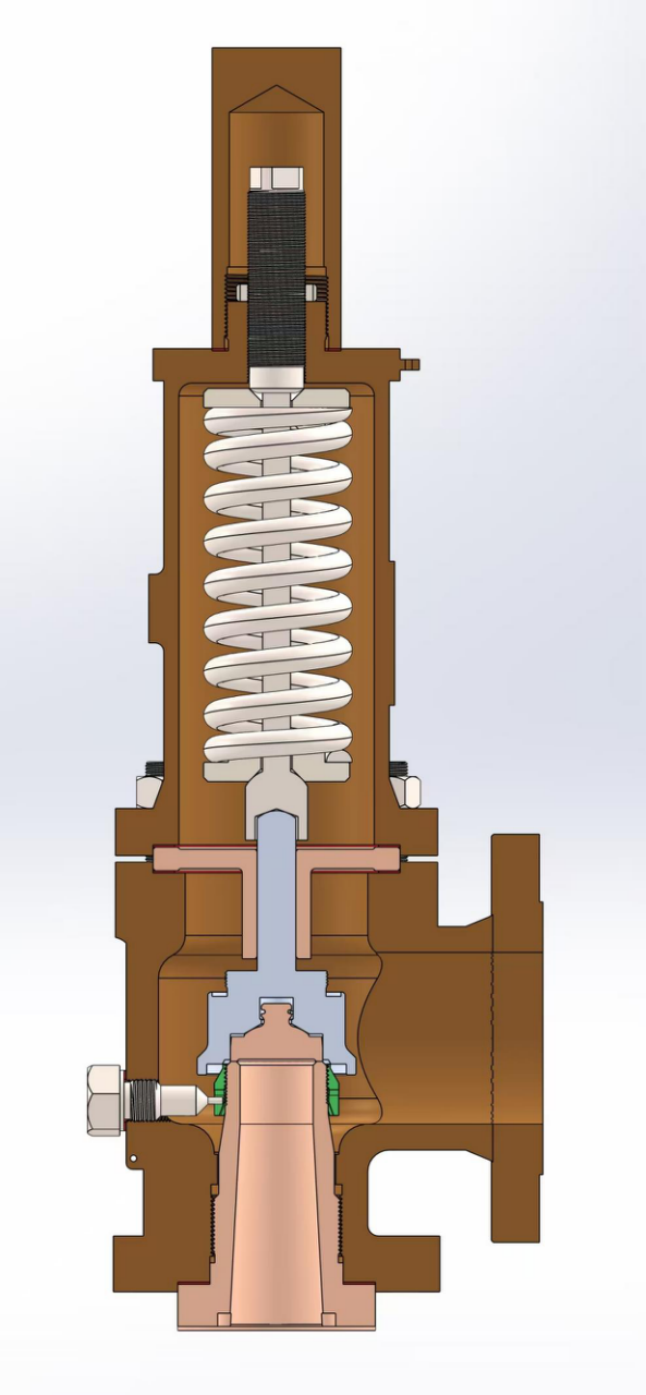
Fig. 1 Cutaway of a conventional spring-loaded safety valve — seat, disc, and spring assembly
1. Equipment That Requires Relief Protection
API 521 requires overpressure protection for pressure vessels, heat exchangers, fired heaters, and any piping sections that can be blocked in by thermal expansion or upstream pressure fluctuations.
Group-protection principle: a relief valve protects a group of equipment — those between two isolation valves and subject to the same overpressure source — rather than each vessel individually. The following overpressure scenarios must be evaluated:
- Blocked outlet — closure of a downstream isolation valve that traps the system under overpressure;
- External heat input under fire conditions;
- Runaway chemical reaction or thermal expansion of the contained medium;
- Loss of utilities (cooling water, electrical power, or instrument air);
- Pressure override caused by failure of an upstream pressure control valve.
In a sulfuric acid plant, the converter, the SO₂ blower discharge buffer vessel, the steam header, and the intermediate-pressure waste-heat boiler steam drum are the key items to be protected.
2. Key Selection Criteria
Valve type: the spring-loaded safety valve is the most widely used type. API 526 defines fourteen standard orifice letter designations from D to T (D, E, F, G, H, J, K, L, M, N, P, Q, R, T), covering the full range of common relieving-capacity requirements. When the backpressure exceeds 10% of the set pressure, a balanced-bellows valve should be selected. Pilot-operated valves can accommodate higher and more variable backpressure and are suited to clean, high-ΔP services.
Set pressure: per ASME Section VIII and API 520, for non-fire cases the maximum relieving pressure is 110% of the design pressure (10% accumulation). For fire cases, 121% (21% overpressure) is permitted.
Backpressure check: for a conventional spring-loaded valve, a backpressure above 10% of the set pressure degrades lift and discharge capacity. A balanced-bellows valve uses a bellows whose effective area equals the seat area, eliminating the effect of backpressure on the set pressure.
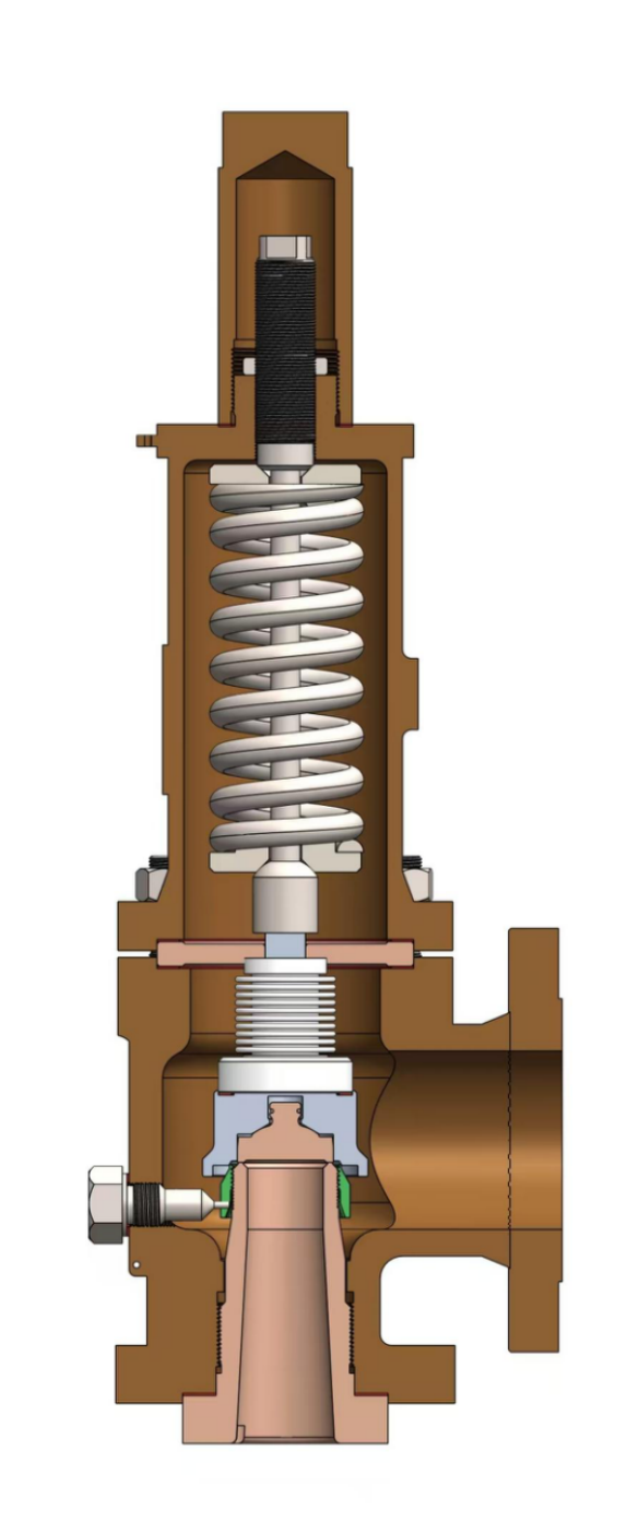
Fig. 2 Cutaway of a spring-loaded safety valve — with bellows assembly
3. Relieving Capacity and Orifice Sizing
The nozzle throat area must be sized for the maximum relieving rate under the abnormal condition. API 520 Part I provides the sizing methods for gas/vapor, liquid, and two-phase flow.
Gas/vapor service (critical flow):
A = (W / (C·Kd·P1·Kb)) × √(T·Z / M)
where:
- A — required effective discharge area;
- W — mass relieving rate (kg/h);
- C — gas coefficient, a function of the specific-heat ratio k;
- Kd — effective coefficient of discharge (0.975 for gas/vapor per API 520);
- P1 — relieving pressure, absolute;
- Kb — backpressure correction factor;
- T — relieving temperature (K);
- Z — compressibility factor;
- M — molecular weight of the medium.
Calculation notes: every abnormal source must be identified individually. For a waste-heat boiler, for example, the relieving rate must include the maximum steam generation plus the additional evaporation caused by fire input heat; otherwise the orifice will be undersized and protection will fail.
Discharge destination: API 521 requires flammable and toxic media to be routed to a flare or a closed collection system. Relieving scenarios that present a vapor-cloud-explosion risk must be addressed through a flare, a low-pressure system, HIPS, or redesign.
4. Installation and Piping Requirements
Inlet piping: API 520 Part II requires the relief valve to be located as close as possible to the protected equipment, and the inlet-piping pressure loss must not exceed 3% of the set pressure (the "3% rule"). Excessive loss causes chattering or delayed opening.
Outlet piping: the outlet pipe must not be supported by the valve body; it requires independent support and must allow for thermal expansion. The discharge line should be arranged for gravity drainage to prevent condensate accumulation from affecting backpressure.
Multiple valves on a common header: when several relief valves discharge into a common header, the accumulated header backpressure on each valve's lift performance must be evaluated.
5. Field Case Study
A 98.5% H₂SO₄ recycle tank in a sulfuric acid plant was designed as an "atmospheric tank" and was not provided with a relief valve. During start-up, the steam tracing valve leaked, the acid temperature in the tank rose, and steam accumulated. The pressure briefly rose to 0.04 MPa, blowing out the manhole gasket on the tank roof and allowing sulfuric acid to escape.
Afterward, per the API 2000 venting requirements for atmospheric and low-pressure storage tanks, a combined breather-valve-and-relief-valve assembly was installed, with a set pressure of 0.03 MPa and a relieving capacity sized for the maximum rate of steam generation.
Key point: an atmospheric design does not mean overpressure can never occur. Heating, chemical reaction, and mis-operation must all be included in the overpressure scenario analysis.
Conclusion
The engineering logic for relief valves can be summarized as: configure valves by overpressure source (group protection), size the orifice for the abnormal flow, select the valve type by backpressure and medium, and control inlet pressure loss to the 3% rule. The API 520/521/526 framework provides a complete chain from scenario identification and sizing to installation verification. A follow-up article will discuss rupture discs and their combined use with relief valves.
References
API 520 Part I / Part II — Sizing, Selection, and Installation of Pressure-relieving Devices, American Petroleum Institute (API).
API 521 — Pressure-relieving and Depressuring Systems, American Petroleum Institute (API).
API 526 — Flanged Steel Pressure-relief Valves, American Petroleum Institute (API).
API 2000 — Venting Atmospheric and Low-pressure Storage Tanks, American Petroleum Institute (API).
ASME Boiler and Pressure Vessel Code, Section VIII, Division 1 — maximum 10% accumulation for non-fire cases and 21% accumulation for fire cases.
Shanghai Xiazhao Valve — pressure relief valve and special valve solutions. For API-standard selection support or technical inquiries, please contact our engineering team.