EN

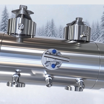
01 | DBB Is a Feature, Not a Valve
A buyer writes double block and bleed into a datasheet. Three quotations return, one DBB, one DIB-1, one DIB-2, and all three describe double isolation. The prices differ by nearly 20%. On paper the three options look like the same promise. In the body cavity they behave in three different ways, and the cavity is where the field problems appear.
This article separates the configurations by what they do to trapped pressure, gives the temperature number that decides whether an external relief is needed, and names the test that proves which configuration was actually delivered.
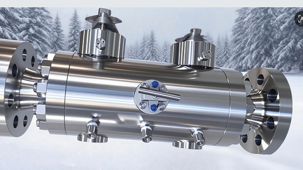
Figure 1. Stainless steel double block and bleed ball valve: two independent ball sections in one body, each with its own operator, and a cavity bleed connection between them. Shanghai Xiazhao Valve.
DBB, double block and bleed, means two sealing elements with a bleed between them. In a trunnion-mounted ball valve the two seats are the two elements and the cavity drain is the bleed. The bleed is not a decoration, it is the proof: close the valve, open the bleed, and no flow means both seats are holding. That is the only in-service verification of double isolation that exists.
02 | SPE and DPE: the Seat Area Ratio
A ball valve seat seals in one direction and moves in one direction. In a single piston effect, SPE, seat, line pressure pushes the seat toward the ball and adds to the sealing force. In a double piston effect, DPE, seat, pressure acts on both sides of the seat, so cavity pressure loads the seat as well, and the seat holds against flow coming from either direction.
The deciding quantity is the ratio between the seat's pressure-actuated area and the area of the sealing contact. Where that ratio is above one, pressure always adds to seat load. Where it is below one, pressure on the wrong side can lift the seat off the ball. That is why the same seat geometry behaves differently under line pressure and under cavity pressure.
Table 1. What each seat type does to the body cavity
Seat type |
Seals against flow from |
Cavity pressure path |
Volume behaviour |
SPE, single piston effect |
Its own upstream side |
Vents back into the line through the seat |
Cavity self-relieves; pressure cannot accumulate |
DPE, double piston effect |
Either side, including the cavity |
Fully trapped; seat blocks the return path |
Cavity holds pressure until externally relieved |
A DBB valve uses two SPE seats. A DIB-1 valve uses two DPE seats. DIB-2 uses one of each. That single ratio, repeated on both ends, is the whole difference between the three part numbers.
03 | The Temperature Number
A trunnion valve that closes on liquid traps a volume between the two seats. Ambient heat expands the liquid faster than it expands the steel around it, and because a liquid is only slightly compressible, the pressure rises quickly. The valve does not need a process upset to overpressure its own cavity, only a warm morning.
Two material properties set the rate: thermal expansion of the liquid and its compressibility. Water expands about 2 x 10⁻⁴ per degree Celsius in the normal ambient band and compresses roughly 5 x 10⁻⁵ per bar, which puts the rise in the region of 2 to 4 bar per degree for a fully liquid-filled cavity. Crude oil expands around four times more per degree and compresses similarly, so it reaches the same pressure in a third of the temperature rise.
Table 2. Ambient rise needed to pressurise a liquid-filled cavity to the class rating
Class |
Rating at 38 C (bar) |
Water, rise required |
Crude oil, rise required |
Class 150 |
19.6 |
approx. 4 to 9 C |
approx. 2 to 4 C |
Class 300 |
51.0 |
approx. 10 to 23 C |
approx. 4 to 10 C |
Class 600 |
102.1 |
approx. 20 to 45 C |
approx. 8 to 20 C |
The ranges are wide because the answer depends on how much of the cavity is actually liquid, on wall compliance and on the fill temperature at closure. They are wide enough to be useful: a Class 150 water valve in direct sun reaches its rating in a single morning, while a Class 600 gas valve on the same rack does not. That is the entire argument for specifying the relief path instead of assuming it.
04 | The Test That Proves the Configuration
Configuration is proven by test, not by drawing. The standard sequence for a DBB valve runs as follows. Close the valve, pressurise one side, hold for the specified period, and verify two things at once: no leakage past the upstream seat, and no flow from the cavity bleed. Then repeat from the other side. A valve that passes both directions has two independent barriers.
A DIB-1 valve behaves differently during that test. Both seats hold against pressure from either side, so isolation is redundant, but the cavity has no return path, and the bleed will keep producing liquid as the trapped volume depressurises. That is the feature the buyer paid for, and it is also the reason DIB-1 requires an external relief device. A DIB-1 valve without a relief valve is a small pressure vessel with a ball inside it.
Three practical checks belong at the factory acceptance test. First, the bleed connection should be a real port of usable size, not a threaded plug with a drilled hole. Second, the test report should record which side was pressurised for each seat, because DIB-2 results are direction dependent. Third, the seat orientation of a DIB-2 valve should be confirmed against the piping layout, since installing it the other way reverses which seat relieves.
05 | Choosing Between the Three
The choice is not about buying more isolation. It is about deciding where the trapped pressure is allowed to go. Table 3 states the decision in the form it usually arrives in a quotation review.
Table 3. Selection matrix for API 6D seat configurations
Question |
DBB |
DIB-1 |
DIB-2 |
Cavity relief |
Automatic, through both seats |
None; external device mandatory |
Through the SPE seat only |
Isolation redundancy |
Two barriers, each one direction |
Two barriers, both directions |
One bidirectional barrier plus one relief path |
Typical service |
General oil and gas, liquid or gas, the default choice |
Critical isolation where upstream failure must not reach downstream |
Where double isolation is required but external relief is impractical |
Watch-out |
Upstream seat failure leaves downstream sealing in one direction only |
External relief device must be specified, installed and maintained |
Orientation sensitive; must match piping layout |
Relative cost |
Base |
Higher, plus relief hardware |
Between the two |
For crude oil export, DBB is normally sufficient: both seats relieve, the cavity self-protects, and the bleed gives maintenance a way to prove both barriers. DIB-1 earns its cost at points where a leaking upstream seat would put product past a barrier that is supposed to be absolute, typically before a storage tank, a metering skid or a maintenance isolation. DIB-2 is the compromise, and it is only a compromise if the orientation is right.
06 | Five Lines for the RFQ
- The configuration by API 6D term, written as DBB, DIB-1 or DIB-2, not as double isolation.
- The cavity relief arrangement, self-relieving seats, external relief valve or vent to flare, named explicitly.
- The line fluid and whether it is liquid or gas, because that decides whether the thermal case exists at all.
- The bleed port size and type, since a plug is not a bleed connection.
- Requirement to record the pressurised side per seat in the test report.
One sentence does most of the work: state the fluid, state the configuration, state where the cavity pressure is allowed to go. Everything else in the specification follows from those three.
Appendix A | Image Asset
Figure 1 is embedded in section 01 at its delivered resolution. The source file is a catalogue image at 625 x 351 px, so re-export from the original artwork rather than from this document before publishing.
Field |
|
File |
assets/xiazhao-dbb-ball-valve.png |
Subject |
Stainless steel DBB ball valve, two operators, cavity bleed between the ball sections |
Embedded size |
625 x 351 px, landscape; low resolution, suitable for web at 15 cm width only |
Alt text |
Stainless steel double block and bleed ball valve with two operators and a cavity bleed - Shanghai Xiazhao Valve |
Web export |
Keep the PNG or export WebP at quality 85; do not upscale beyond 625 px width |
Caption |
As printed under Figure 1; do not rewrite |
Appendix B | Standards Referenced and Data Notes
API 6D. Specification for Pipeline and Piping Valves, 24th Edition. Annex E defines the DBB and DIB features; Sections 3.1.10 and 3.1.11 define single and double piston effect seating.
ASME B16.34. Valves - Flanged, Threaded, and Welding End. Class 150, 300 and 600 pressure ratings at 38 C for Group 1.1 carbon steel are 19.6, 51.0 and 102.1 bar respectively.
API 598. Valve Inspection and Testing. Defines the shell and seat test sequence used to prove the configuration at FAT.
ISO 5208. Industrial valves - Pressure testing of metallic valves. Leakage rate classes used when the acceptance criterion is quoted by class rather than by standard.