EN
EN


Full-Chain Engineering Judgment for Austenitic Stainless Steels and Cryogenic Safety Valves in Liquid Hydrogen and Liquid Helium Service: From Composition Calculation to Procurement Specifications
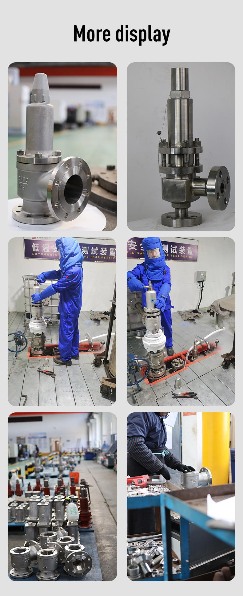
Two Lines of Defense, One Safety Objective
Liquid hydrogen boils at -253℃, and liquid helium can reach as low as -269℃. In this extreme cryogenic range, engineering safety depends on two complementary lines of defense, both of which are closely related to the low temperature service suitability of cryogenic safety valves.
The first line of defense is material stability. Pressure-containing components of liquid hydrogen and liquid helium equipment must be made of highly stable austenitic stainless steels, and must not spontaneously transform into brittle martensite under cryogenic conditions. The core engineering criteria are the austenite stability coefficient Δ and the martensite start temperature Ms, which are also essential indicators for cryogenic safety valve material qualification.
The second line of defense is overpressure relief. In closed liquid hydrogen and liquid helium vessels, continuous heat ingress causes vaporization and pressure buildup, making cryogenic safety valves the final mechanical overpressure protection barrier for cryogenic systems. The dedicated material, reliability at -253℃ / -269℃, low-temperature sealing performance, anti-icing design, and installation configuration all determine whether this defense remains effective in real service.
The critical intersection of these two defenses is often overlooked: all pressure-containing parts of the cryogenic safety valve, including the body, bonnet, and seat, must meet the same Δ and Ms criteria as the liquid hydrogen/liquid helium vessel material. If a valve is selected only as “stainless steel” without Ms verification, martensitic transformation may occur during cooling before the valve even opens, leading to seat damage, guide component failure, and loss of overpressure protection.
This article integrates material calculation, data validation, standard requirements, safety valve selection, failure analysis, and procurement acceptance criteria into one engineering judgment chain for cryogenic safety valves in LH2 and LHe service.
Part 1. Material Criteria: Engineering Meaning of Δ and Ms for Cryogenic Safety Valves
1.1 Why “Ordinary Austenitic Stainless Steel” Is Not Sufficient for LH2/LHe Cryogenic Safety Valves
Austenitic stainless steels are widely used in cryogenic equipment because their face-centered cubic structure retains toughness at low temperatures. However, common grades such as 304, 316, and 316L may undergo spontaneous martensitic transformation under -253℃ liquid hydrogen or -269℃ liquid helium conditions, especially under combined mechanical stress and thermal cycling.
For a low temperature safety valve, martensitic transformation is a critical failure risk. Brittle martensite can cause seat leakage, stem sticking, guide component damage, and even body cracking. Therefore, material selection for cryogenic safety valves must not rely only on the stainless steel grade; it must be verified by chemical composition calculation.
1.2 Austenite Stability Coefficient Δ for Cryogenic Safety Valve Material Qualification
The Δ coefficient is used to evaluate the resistance of austenitic stainless steel to martensitic transformation under cryogenic conditions. It is a prerequisite criterion for cryogenic safety valve material acceptance.
Formula:
Δ=Ni+0.5Mn+35C−0.0833(Cr+1.5Mo−20)^2−12
Where all elements are in weight percent (%).
Engineering criteria for cryogenic safety valves:
- Δ < 0: Higher risk of martensitic transformation, significant toughness degradation under cryogenic conditions; not acceptable for pressure-containing parts of LH2/LHe safety valves.
- Δ ≥ 0: Good austenite stability and low transformation tendency; suitable for cryogenic safety valves in liquid hydrogen and liquid helium service.
1.3 Martensite Start Temperature Ms: Service Temperature Threshold for Cryogenic Safety Valves
The Ms temperature defines the minimum temperature at which martensitic transformation may start. It is the key quantitative parameter distinguishing liquid hydrogen-grade and liquid helium-grade safety valves.
Formula:
Ms=1.875(14.6−Cr)+110(8.9−Ni)+60(1.33−Mn)+50(0.47−Si)+3000[0.068−(C+N)]−321.8
Service criteria:
- For liquid hydrogen safety valve (-253℃ service): Ms ≤ -253℃
- For liquid helium safety valve (-269℃ service): Ms ≤ -269℃
A lower Ms value indicates better austenite stability and improved resistance to brittle transformation during cryogenic shutdowns, pressure fluctuations, and long-term standby.
Part 2. Data Validation: Small Composition Changes Make a Big Difference for Cryogenic Safety Valve Suitability
2.1 Chemical Composition Samples
Element Sample A Sample B Sample C
C 0.025 0.060 0.070
Si 0.50 0.45 0.50
Mn 1.50 1.30 1.40
Cr 17.0 16.5 16.6
Ni 11.0 11.2 11.4
Mo 2.20 2.20 2.15
N 0.030 0.080 0.095
2.2 Calculation Results and Cryogenic Safety Valve Suitability
Index Sample A Sample B Sample C
Δ -2.18 +2.67 +4.31
Ms (℃) -287.6 -315.2 -331.8
Judgment Δ < 0; high transformation risk; not acceptable for LH2/LHe safety valves Δ > 0, Ms ≤ -269℃; suitable for LH2 and LHe safety valves Best stability; preferred material for liquid helium safety valves
2.3 Key Observations for Cryogenic Safety Valves
Carbon and nitrogen are the most effective stability levers. From Sample A to Sample B, only modest increases in C and N raise Δ from negative to positive. The term 3000[0.068-(C+N)] is highly sensitive; insufficient C+N content can significantly increase Ms and raise the risk of brittle transformation in cryogenic safety valves.
Nickel contributes linearly, while C and N have a stronger stabilizing effect. From Sample B to Sample C, a small Ni increase combined with slightly higher C+N produces a notable improvement in stability and reduction in Ms.
Molybdenum is not the primary stabilizing factor. Mo appears as a negative term in the Δ formula. The better cryogenic performance of 316L compared with 304L comes mainly from higher Ni and tighter composition control, not from Mo itself.
2.4 Interpretation of Ms Values Below Absolute Zero
Samples B and C calculate to Ms < -273.15℃, which has no physical meaning as a real transformation temperature. However, in engineering terms, such results indicate that the austenite is extremely stable at the actual -269℃ liquid helium service temperature, with negligible driving force for spontaneous martensite formation.
Practical interpretation for cryogenic safety valves:
- Ms -269℃: Actual transformation temperature may be reached in LHe service; not acceptable for liquid helium safety valves.
- -273.15℃ < Ms ≤ -269℃: No spontaneous martensitic transformation under LHe conditions; acceptable.
- Ms < -273.15℃: Mathematical extrapolation only, but indicates excellent austenite stability and large cryogenic safety margin.
Part 3. Mandatory Requirements for Cryogenic Safety Valves in Extreme Low Temperature Service
3.1 Low Temperature Impact Toughness
For service temperatures below -196℃, the material used in cryogenic safety valves must be impact tested at the design temperature:
- Liquid hydrogen service: impact test at -253℃
- Liquid helium service: impact test at -269℃
Acceptance criteria:
- Average KV2 ≥ 54 J
- Average lateral expansion LE ≥ 0.53 mm
If tested at -196℃ instead, more stringent values are required:
- KV2 ≥ 70 J
- LE ≥ 0.76 mm
3.2 Ferrite Content Control
Ferrite is a brittle phase that can act as a crack initiation site under cryogenic conditions. For cryogenic safety valve pressure-containing parts, ferrite content should be ≤ 3%, tested according to GB/T 13305.
3.3 Batch Verification by Actual Chemical Analysis
Δ and Ms must be calculated from the actual chemical analysis results in the material test report, not from theoretical values. Each batch of cryogenic safety valves should be verified individually.
Part 4. Cryogenic Safety Valves: The Last Mechanical Barrier for LH2/LHe Systems
4.1 Why Dedicated Cryogenic Safety Valves Are Required for Liquid Hydrogen and Liquid Helium
Liquid hydrogen and liquid helium have extremely low boiling points. In closed vessels, continuous heat ingress causes vaporization and pressure buildup. Without reliable relief devices, overpressure can lead to catastrophic failure.
Compared with ordinary or even general low-temperature valves, cryogenic safety valves must withstand extreme temperatures and maintain sealing and cycling reliability. Common spring materials and sealing systems may suffer from spring embrittlement, seat leakage, ice formation, stem sticking, and seal shrinkage at -253℃ / -269℃.
The key domestic standard is GB/T 46630-2025 Safety Valves for Cryogenic Containers, effective from 1 May 2026 and modified from ISO 21013-1:2021. It applies to cryogenic gas relief valves below -10℃ up to DN150, and classifies them into:
- Class A: valves that may operate during normal service; seat leakage must be verified after 1000 repeated test cycles.
- Class B: valves that remain closed during normal service; seat leakage must be verified after 20 cycles.
The fundamental rule is: all pressure-containing parts of the cryogenic safety valve must meet the same Δ and Ms requirements as the vessel material.
4.2 Case Study 1: CERN LHC – 400 Cryogenic Safety Valves for LHe Service
The CERN Large Hadron Collider (LHC) is one of the most demanding liquid helium safety valve applications in the world. Its 27 km superconducting system includes approximately 400 cryogenic safety valves protecting the superfluid helium magnet vessels at 1.9 K (-271.25℃), with set pressures around 17 bar and full lift around 20 bar.
The main challenges include:
- Operation in superfluid helium near absolute zero
- Very low heat ingress
- Resistance to radiation
- Remote control capability
- Stable set pressure under backpressure
- No icing or sticking during cycling
This case demonstrates that cryogenic safety valves for LHe service are not standard commodities. They require specialized engineering, including low-thermal-conductivity stems, bellows seals, thermal compensation structures, and remote actuators. Major suppliers in this field include Toko Valex and WEKA AG.
Key takeaway: Do not select liquid helium safety valves based only on LN2 experience. The gap from -196℃ to -269℃ is more significant than the gap from -196℃ to ambient temperature.
4.3 Case Study 2: Herose – Cryogenic Cycling Performance Data
Herose is a global supplier of industrial cryogenic valves, with safety valves capable of operating down to -270℃. Its products cover oxygen, nitrogen, argon, CO2, helium, and hydrogen service, with an annual output of more than 200,000 valves.
One important durability test demonstrated that Herose safety valves achieved:
- 144,000 cycles at ambient temperature
- 2,000 cycles under cryogenic gas conditions
In a specific 06388 type test under “no gas withdrawal” conditions, the valve achieved nearly 1,000 operations in a liquid nitrogen vessel with almost no gaseous buffer space. This proves that cryogenic safety valves must remain reliable even under unfavorable transient conditions such as low liquid levels, transport, or temporary operation without stable gas space.
The Herose 06011 type stainless steel cryogenic safety valve covers -255℃ to +65℃, making it suitable for LNG and hydrogen service. It has TÜV type-test certification, and hydrogen service versions require shell and seat leakage testing with helium or a 95% nitrogen / 5% hydrogen mixture.
4.4 Case Study 3: Equinor Hammerfest LNG – Hidden Risks During Maintenance and Isolation
On 31 May 2023, a major gas leak occurred at the Equinor Hammerfest LNG plant. The direct cause was related to an open vent plug with left-hand thread on an upstream pipe of a safety valve during insulation removal work. The operators were not familiar with the special connection and did not close it properly.
The leak lasted about 6.5 hours, released approximately 9,300 kg of gas, and caused an 8-day shutdown.
This case shows that even if the cryogenic safety valve itself is functional, isolation, venting, and maintenance procedures can disable the protection system. For LH2/LHe safety valves, the following are critical:
- Clear operating procedures for unconventional vent components
- Permanent identification of normal open/closed positions
- Lockable or carve-open isolation configurations
- Human-factor review of maintenance interfaces
4.5 Selection Parameters for LH2 and LHe Cryogenic Safety Valves
Parameter LH2 Cryogenic Safety Valve (-253℃) LHe Cryogenic Safety Valve (-269℃)
Body material Austenitic stainless steel, Δ ≥ 0, Ms ≤ -253℃ Austenitic stainless steel, Δ ≥ 0, Ms ≤ -269℃
Seal design Metal seat or carbon-filled PTFE with cryogenic verification Metal seat preferred; non-metallic seals require special validation
Minimum design temperature ≤ -255℃ ≤ -270℃
Key tests Seat leakage and cycling reliability at -253℃ Cycling reliability and seat integrity at -269℃
Applicable standards GB/T 46630-2025, ISO 21013-1 GB/T 46630-2025, EN 13648-1 with special validation
Note: GB/T 40011-2021 covers pilot-operated cryogenic safety valves down to -196℃, which is not sufficient for -253℃ LH2 or -269℃ LHe service. For these extreme conditions, selection must rely on manufacturer type-test data and equivalence to international standards such as ISO 21013-1 and EN 13648-1.
Part 5. Three Core Procurement Requirements for Cryogenic Safety Valves
5.1 Requirement 1: Material Ms ≤ Service Temperature
The most common procurement mistake is specifying only “austenitic stainless steel” without defining stability criteria.
Procurement specification clause:
The pressure-containing parts, including body, bonnet, and seat, shall be made of austenitic stainless steel. The Supplier shall provide the actual chemical analysis from the material test report and calculate Δ and Ms in accordance with the formulas above. For liquid hydrogen service, Ms ≤ -253℃; for liquid helium service, Ms ≤ -269℃. In all cases, Δ ≥ 0 is required. Ferrite content shall be ≤ 3% according to GB/T 13305. Ms values below -273.15℃ shall be accepted as meeting the Ms requirement.
Additional verification:
- LH2 service: -253℃ impact test report
- LHe service: -269℃ impact test report
- If tested at -196℃, require KV2 ≥ 70 J and LE ≥ 0.76 mm
5.2 Requirement 2: Cryogenic Cycling Test Data Shall Be Verified
Many cryogenic safety valve failures are caused by seat degradation or sticking after repeated cycling, not by single opening failure. Procurement specifications must require verifiable cyclic performance.
Procurement specification clause:
The Supplier shall provide cryogenic cyclic performance test data from type-test reports or manufacturer-validated durability records. The test temperature shall be no higher than the minimum design temperature of the valve. The number of cycles shall be at least the manufacturer’s declared value for cryogenic service. After cycling, the seat leakage rate shall meet the requirements of GB/T 46630-2025 for the specified class. Valves without cryogenic cycling data shall not be accepted for LH2/LHe service.
Acceptance check:
- Review the cryogenic test section of the type-test report, not only the ambient temperature part
- No adjustment or maintenance of the test valve is permitted between cryogenic cycles
- If only LN2 data exists, it must be clearly identified as not equivalent to LHe validation
5.3 Requirement 3: Isolation and Vent Configuration Must Prevent Human Error
Even a fully functional cryogenic safety valve can be defeated by poor isolation design.
Procurement specification clause:
Isolation valves shall preferably not be installed upstream or downstream of the cryogenic safety valve. If process requirements make isolation necessary, the configuration shall use carve-open, lock-open, or double-block-and-bleed arrangements to ensure that at least one relief path is always available. Any manual valve in the vent line shall be locked open or carve-open and permanently marked: “Safety Valve Vent Line – Do Not Close.” Unconventional components such as special vent plugs shall have permanent operating instructions. The Supplier shall provide an installation and isolation schematic for review by the Buyer’s process safety engineer.
Part 6. Closing the Safety Loop: Material Stability and Cryogenic Safety Valves
Austenitic stainless steel stability ensures that vessels and pressure-containing parts do not become brittle at cryogenic temperatures. Cryogenic safety valves ensure that the system does not rupture due to overpressure. These two functions are complementary and equally important.
The most practical recommendation for LH2/LHe projects is to include three requirements in the cryogenic safety valve procurement specification:
- Material Ms ≤ service temperature
- Verified cryogenic cycling performance
- Isolation configuration with human-error prevention
These requirements are more meaningful than simply referencing a standard number. They should be placed in the “Technical Requirements” section as independent clauses, not hidden under “General Requirements.”
Conclusion
For cryogenic safety valves in -253℃ liquid hydrogen and -269℃ liquid helium service, there is no universal off-the-shelf solution. Material calculation, low-temperature testing, sealing reliability, and system isolation must all be verified together.
Δ indicates the risk of martensitic transformation.
Ms defines the minimum service temperature threshold.
Cryogenic cycling data proves sealing reliability after repeated operation.
Isolation and lock-open requirements prevent human factors from disabling the relief path.
The real safety guarantee for cryogenic safety valves in extreme low-temperature service lies in the combination of:
- Actual chemical analysis
- Low-temperature impact test results
- Ferrite control
- Cryogenic cyclic performance verification
- Isolation and error-prevention design
This is the core engineering criterion for cryogenic safety valves in liquid hydrogen and liquid helium service, and the essential basis for safe and reliable operation of ultra-low-temperature hydrogen and helium systems.